Build Log...
Ok I have always hated how "blogs" are backwards! You know how the latest entry is at the top of the page and then as you read down you go "back in time". This does not flow nicely when reviewing a build sequence so I have decide to do as I think it should be, like a story, you start at the beginning and work down. - maybe it just?? =)
The story so far...
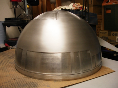
300mm Dome - Battle of the Spin Lines
Progress on the dome has been slow. I've managed to cut out the dome panels and make good (which took way longer than I thought it would). The main problem with the dome is trying to get rid of the spin lines. The removal of these lines is slow and very laborious. The method I've used was lots of wet and dry paper, first using it dry and then adding water to help. Adding water does seem to help and definitely reduces the Alu dust (which you must take precautions for!), although the life of the paper is shortened. In the end I couldn't take anymore and brought out the big guns, the electric orbital sander :) At first this approach scared the life out of me, but using a slow speed and a circular motion got rid of the lines fairly quickly. Finishing off with hand sanding (again) and a final touch of wire wool to reduce the sanding lines.
As I'm going of a dull dome this is where I'll leave it. The only question is do I lacquer the dome or leave it to oxidize...
All that remains (all!) is to cut the panels in the inner dome and try and get the two domes to fit snuggly. At the moment there's a bit of a gap (see below), although sanding the domes is reducing this effect, more on this later...
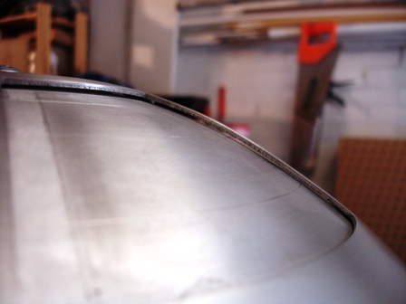
In the pic below you can see the spin lines on the inner dome still.
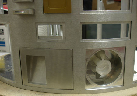
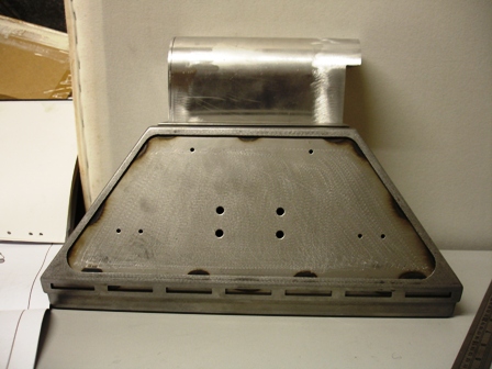
Central Vents
When you first get these you look at them trying to figure what goes where and is more like a Chinese puzzle! I strongly recommend finding the plans from the forums to see how they go together, as I promise you won't get it right on your own.
The biggest problem and my only mistake (so far) is that when these were designed by Tom Douchet it was suppose to be made of a thinner Alu sheet, however the metal shop switched to a slightly thicker spec. Not a problem you might think however all the laser cuts were made for the thinner spec sheet and not updated! So every slot and there's a lot had to be filed down so the pieces could be slotted together. The problem was the slots are only a few mm thick and no file would fit :( To make matters worse the tolerances are very small and an end bit on the side panels broke off as the force of filing was to much on such a thin piece. Lucky this isn't seen when mount.
The mistake I made when widening the slots on the side panels. When filing I didn't file the same side of the slot on both sides. So on one side I filed the top of the slot and the other I filed the bottom. This resulted in the louvers being slightly angled :(
Do not make the same mistake!
Update: I later bought new Center Vents.
The Battery Boxes
Just got these and decided to mount them to the feet via a slotted hole so they can be popped off when needed. All easy, a hole in the box to insert a bolt is used to fit into the slotted hole on the foot. Just be careful, the hole needs to be very close the edge of the box and a weld line (which isn't welded all the way on my boxes).
Image showing Ryan's Battery box and JAG's Steel outer foot.
Test fit - I couldn't resist!
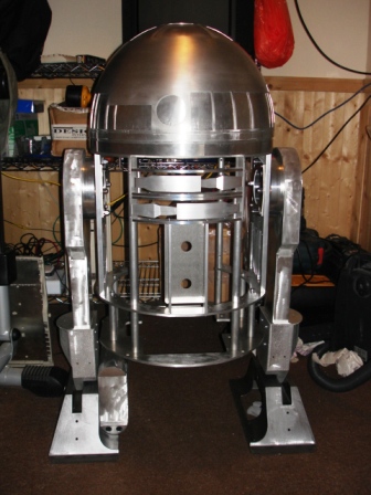
Well the ankles just arrived which means I can make my Droid stand on it's own two feet! :)
After squeezing the ankles in to the feet as there is no tolerance. This needs to be addressed later so the paint finish won’t get stripped off. When bolted together and making sure I had the locking plate in place first. It finally did it! It now stands up on its own (although not too stable).
At this point you realize how big this is going to be and it's bigger than you think! ;)
Electrickery bits - The LED Wars
28/12/08
Over the Christmas period I decided to get to grips with the JEDI DISPLAY and the task of soldering hundreds of LEDs.
I ended up doing a few every night and to be honest I finished it in about 3-4 days, which wasn't too bad.
The trick is to solder one LED at a time and trim the leg then move on to the next. I found it easier to work vertically, that way the previous LED doesn't get in the way (you'll figure it out). I finally plucked up enough courage to power it up and, nothing happened :(
After chatting with Scott (from JEDI DISPLAY) he came up with a few ideas which did help, I managed to get the Rear Logic Display working although a few LEDs needed re-soldering, the Front Logic Displays however didn't work at all. I did prove the boards were right by connecting it to the RLD output and they worked (again some LEDs needed to be redone).
But it wouldn't work when connected to the correct output. After searching and trying several things Scott came up with I found the problem! After scouring the PCB with a magnifying glass I noticed that only half the pins on a surface mounted IC were soldered. I managed to use an iron to solder these missed pins and then it all worked :)
Even got the LCD display working and the PC talking to the board to display messages :)
The real head scratcher is how all the boards connect to each and realizing that the Display board controller needs to be powered(?!) Oh and read the MANUALS!!!
Update:
If you want to control the board via the PC using their software you need another cable! The USB connector you get in the kit is ONLY for programming the flash memory with Jawa Script. For PC usb control you need this "USB-serial TTL cable,FT232RQ,TTL-232R".
Cutting the Dome - HP cut-outs.
25/01/09
Again this is scary to start with but make sure the outer dome is on and level and mark ALL the panels you intend to cut. I followed another builders tip on cutting and it seems to be ok, so far ;)
The first thing I did was mark the panels and then mark and offset line around the edges. This will be the rim where the panels rest upon. This offset is also useful where the Holo Projectors pass through. The process I used was to drill lots of small holes on the offset mark. When complete change the drill bit size to something 2-3 times larger and redrill the holes you've just drilled, the larger hole will then connect to the hole next to it and eventually you will have a jagged piece of AL will fall out. Once done it's time to file and file and file... You will find even though you filed to line the HP will still not fit through the hole and will need a bit more taken off. Also when you get to this point use a bottle with a pointed top and wrap some Wet and Dry around it and spin the bottle, this will give a uniform smooth finished hole :).
Repeat for the other circular holes.
As for the Pie panels and other panels I'll let you know ;)
Dome Motor - Control, Control you must learn control.
01/02/09
Well I got the bits from Atomic Pickle and the power board from Dan. The power board helps to distribute power at different voltages from a single powers source.
I wired up a battery (12v, 7Ah) that I had lying around and connected the Jedi Display because and a RC receiver. The RC receiver I'm using is a Spektrum BR6000, this has 6 channels all with safety cut out so when things go wrong your droid won't run away at full speed! The Receiver connects to a speed controller (Vantec RET411P) and in turn connects to the motor. It is that simple (once you "bind" your controller to the receiver) and it just worked. Just make sure you read ALL the instructions first and don't forget to fuse the + positive from the battery or you could burn it all out :(
Feet and Braided Hose.
03/04/09
Test fitted all the feet and components. You part designers need to think how these things are attached more, or you have really small hands ;)
Used some of my braided hose which was much better than I expected :)
Dome Panels - No more sanding! Well for the panels...
02/05/09
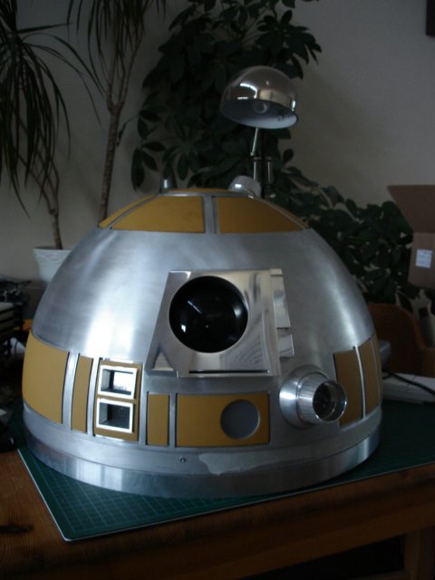
Well I popped into Halfords today to look at paint primers and colours and saw something of interest, "Filler primer". This stuff is use to as a primer but then you sand it down to get a smooth surface before spraying (I need about 3 coats between sanding). Well this worked a treat on my dome panels where the spin lines are really bad (see 300mm dome above). Oh it yellow thus the colour of R2 in the pic, which is really growing on me...
Also I have the JEDI Display installed in the dome too now :)
The radar eye isn't painted as it already super smooth (thx David :))
Note: Milk or Screen wash bottles make good PSI diffusion lens.
Audio System - Can you hear me at the back...
14/05/09
I was working on something in work the other day and suddenly thought, this would be good for R2 (this happens a lot).
I was using a Vmusic2 module which is a little (really little) USB mp3 player for projects and other things (PICAXE etc.). Basically it's a MP3 player that you stick a USB memory stick in and it plays sounds, you control it via RS232.
RS232 although old school is still pretty huge in the home automation world. So after some quick soldering, I hooked this up to my laptop (using TTL cable adapter) and amp.
Now on pressing a button on the laptop, R2 makes a noise. The best thing about this is you can have unlimited sounds (memory stick size applies) and just tell the unit to play specific a mp3 file.
I realize this isn't ideal for an R/C R2 but if you using a micro controller or wifi setup then its a simple matter of sending a RS232 string to the unit.
Also for the speaker and amplifier system, I've been looking around and scouring the net when the answer was literally under my nose :) PC speakers! I have a ton of old PC speakers in boxes and on investigation realized that most are 12V DC and have a built in amplifier usually inside the speaker (The ideal speakers are the ones without the base unit just a left and right speaker. One of them is the amp and the other is just a speaker).
I gutted the speaker with amp and put it in place and wired it to my power board which is also 12V. I might use the other speaker cone too for extra loudness and turning the volume up to 11 ;)
The cheapest place I found was surprisingly RS Components @ £20.90
You'll also need a TTL cable for RS232 control. This is NOT a normal pins 2,3 and 5 cable, that will fry the unit! You must get the correct voltage TTL cable for the unit. I got one from rltechnologies which covers all the voltages ( 3-5.5v).
The best thing is this is the same unit that is used for the JEDI control system so if you can't wait for that, use this now to impress or drive away your friends ;)
Used some of my braided hose which was much better than I expected :)
Catch-up - In perfect hibernation...
23/01/10
What have I been up to all year?? Well the build has been pretty slow the second half of 2009 so here is a quick catch up of what I've been doing:-
- Dome Pie panels - All Pie panels have been cut out. The cut-outs made larger and cleaned up so hinges work and are all the same size now.
- Working on electrical system design. Purchased components for switches and fuse and cables.Then realized all my illuminated switched are for AC circuits only.
- Fitted motors into feet and cleaned up Battery Boxes, filed motors to fit into battery boxes.
- Fitted skins onto frame to work out fixing methods (still working on it...)
- Trying to fit hinges on panels. Had lots of problems until made holes larger. Unfortunately I now want to make the panels open the "other" way from everyone else, so need to mod hinges, but does work!
- Test fitted legs to frame.
Drive System - It's Alive! (almost)...
Today I decided to test out the electrical system and RC control. Well I wired it all up and checked and double checked, then thought "what the hell" and turned it on :)
It worked! With a little tweaking R2 was driving around and bumping into things, hey it's my first time driving this thing!
Well lots of things reveal themselves when it starts to move. The need for foot/ankle locks for a start. The most surprising thing though was it was all powered from a single 12V 7Ah battery (like the ones in a UPS) and was happy driving around for quite a bit and still kept going :)
I'll try and put some more images, schematics and designs of what I've done.
But for now here is a video:-
Catch-up (again!) - Progress so far...
24/02/11
This is what I have been done, since the last update. Again the overall progress has been slow but have made steps towards the end. Here is a list of what's been happening:-
Most work has been directed at redesign or the electrical system. I philosophy is to make a droid as if it was a "real" droid and a tech tool to be used. (yeah I know it sounds funny).
So the final plan is to have removable modules of each of the major systems and these will be removable and upgradable without out to much fuss. The other plan is if I ever make a 2nd droid I can switch systems between them quickly and easily. This will help reduce costs and duplication of expensive electrical components. Anyway that's the plan but lets be honest I need to get it working first :)
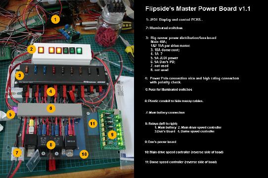
So this is my first step at a Master Power Board. It's purpose is to deliver power to all systems and distribute it safely and self protected fuse wise. Here is my first attempt, it is fully self contained and is easily removable from the droid with slot-in connections to power dome and feet motors.
I will post a schematic of the circuit as and when I find it?!?
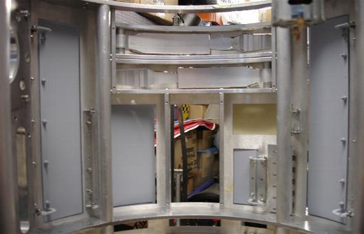
The other progress made is with the skins and body doors. All the front skins have been cleaned up and fitted to the frame. Although a little fiddley I eventually got both front and back fit probably on the frame with no "loose" bits.
Again my philosophy is everything is upgradable so this means no glue (which so far has been easy).
The hinges of the body doors and other parts were fitted like on the dome. Holes drilled and countersunk on the inner skin and these holes and screws are hidden by the outer skin. This process works nicely for all hinges and Power Coupler Octagonal Port and Pocket Vents. Although the pocket vents need to be modified (more later).
Like I said before the no glue rule runs against the grain of a lot of builders, but not all. The doors have been my first challenge. I initially glued the hinges to the back of the door panel. This did work but I noticed that if the doors were pulled of even if the door closed too quickly slamming shut it occasionally came off, even using JB Weld. So after thinking about it trying to come up with ways of not piercing the door panel, it hit me. Well I've been making things difficult and wanting everything to look nice and clean and shiny aluminium. I had a change of thinking and thought "how would they do this on a car" well they would screw or rivet it file it down and cover it with filler and then paint it and you would never know! So this is my thought process know if it's going to be a painted surface then use filler to hide your work. This approach made fitting the doors much easier and removable lots of holes drilled through the door panel and counter sun as before. The only difference is the door panel surround does not cover these holes, that's where the filler comes in :)
This all works fine, however if you use Nyloc nuts the tension is too great and will break the filler covering the screws. I have tried JB welding screws in panel but so far no luck. Normal nuts on seem ok but you still need to be careful... Any ideas?
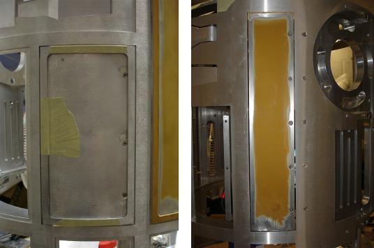
Ok now to the ports and vents.
The first thing I noticed was that my Power coupler is square and not round. David Shaw's Coupler is pretty much 1 lump of aluminium and so the skins needed to be trimmed in order to fit nicely. The Octagonal port is straight forward using the countersunk screw approach as they are fully covered by the outer skin.
The pocket vents although nicely made are like so many other parts have no way of actually fixing them!?! (I wish the council would enforce fixing methods in part runs also). Ok moan over :) By fixing (gluing and screwing) tabs to the rear of the pocket vent they act as a clamp and mounting point again easily removable when needed.
Inner View
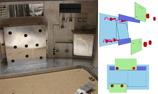
Outer View