Build Log...
Part II of the build...
Prepare for Hyperspace!
Catch with build progress and there's a lot!
Mid 2011.
At around this time many things were coming together and unfortunately I have lost the notes of the build during these times (that's the reason for a blog so I wouldn't forget!).
Ok here is what I remember.
The event at Earl's Court London, LLFC 2001 was rapidly approaching so I wanted to attend with a drive able droid! So I planned months in advance to get things ready... Ok who am I kidding, with about 2 weeks to the event I started throwing things together!
Here are some of the steps and issues I hit along the way.
The basic build was all working at a component or testing on a work bench I just hadn't put it all together!
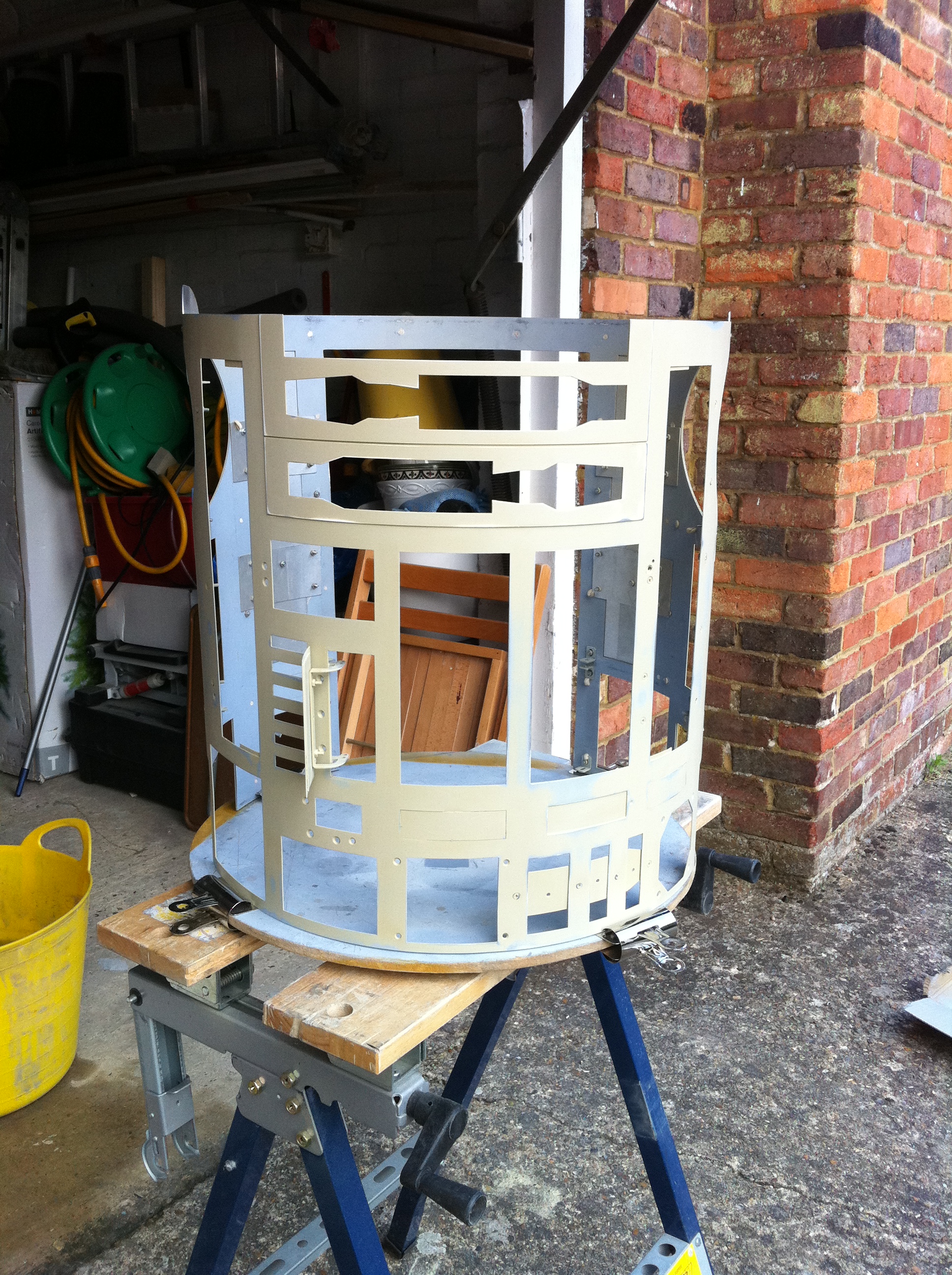
One thing I wanted was a rear panel hatch to help install the insides so I dremelled off the whole rear section panel for a full height door.
Also all the panels were attached again with my thinking that everything can be undone take apart if needed. I used the same procedure of counter sunk screw fixing as previous shown on the front skins. Initially I wanted to try and rivet the panels and skin layers on this however didn't work out for me and I ended up having to drill out all the rivets. After this my rear panel was full of holes and I thought I ruined the skin, then I thought of car filler! This saved me and actually helped me speed up the build process! As I thought everything is going to be painted any filler would be unnoticed so I was not too scared about making mistakes :)
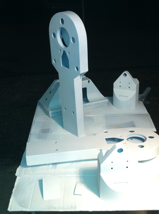
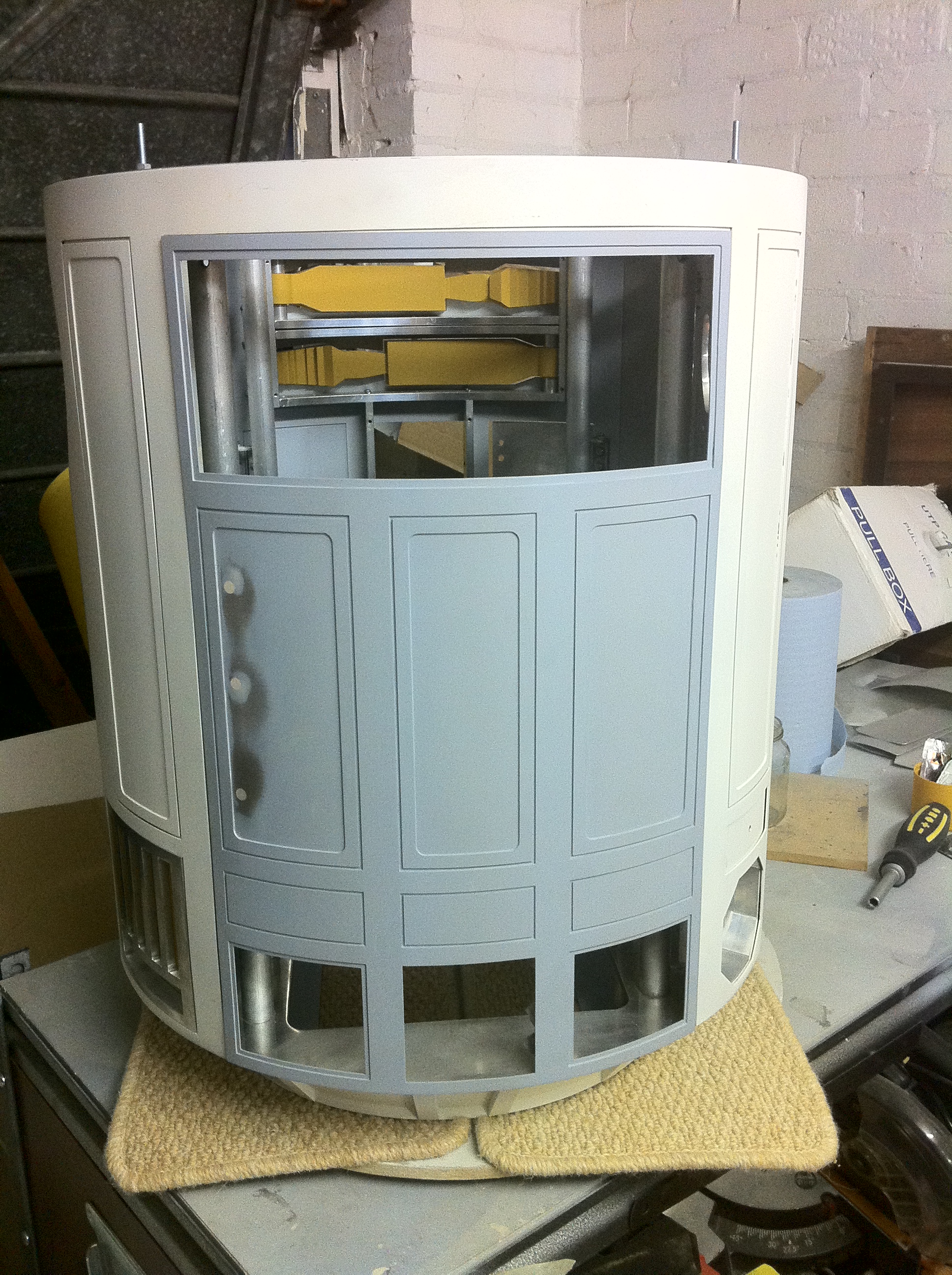
Once the panels and skins were together I primed and painted all the skins.
Here are the general painting notes I made:-
There are 2 ways I know of to get rid of it. Either burn it off with acid or sanding it down. By doing this gets rid of the oxide layer and allows the paint to bond with the actual metal and not the loose oxide layer, remember the oxide will return!
First thing was to clean the metal. Hot soapy water to remove the grease and dirt and then dry it 100% paint and water doesn't mix well!
1. Use an Etch Primer. I use this from Halfords (which surprisingly is the cheapest place I found). U-POL Acid #8 Etch Primer
Or Rub down with steel wool of fine wet and dry to get rid if the oxide layer then wash, but you need to be quick! This method is not as reliable as the using etch just cheaper 
2. Then use a primer. OR If the surface/part your are painting has work marks from sanding and cutting etc. use a high build primer or filler primer. This is a special type of primer that you spray on, wait for it to dry then sand it all off. Ok not all of it, what is left is in the dents and scratches of the surface, you need to use a flat sanding block ideally to make sure the recesses are left unsanded. You then repeat the process several times (spray then sand) until the primer has filled all the scratches and is sanded smooth with the with the surrounding surface. When a final coat is applied a superior finish will be achieved and be baby smooth 
Again I use this U-POL High #5 High Build Primer or this Halfords Filler Primer
3. Then a final coat of your colour choice and finish.
The Yellow parts are actually Halfords Filler primer colour. Rub it down and it looks nice and smooth.
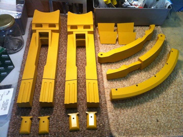
You may notice that 2 of the foot detail pieces are glossy. This was a test with a cleat lacquer.
Back to rear panel I had to devise a catch/locking mechanism and quickly!
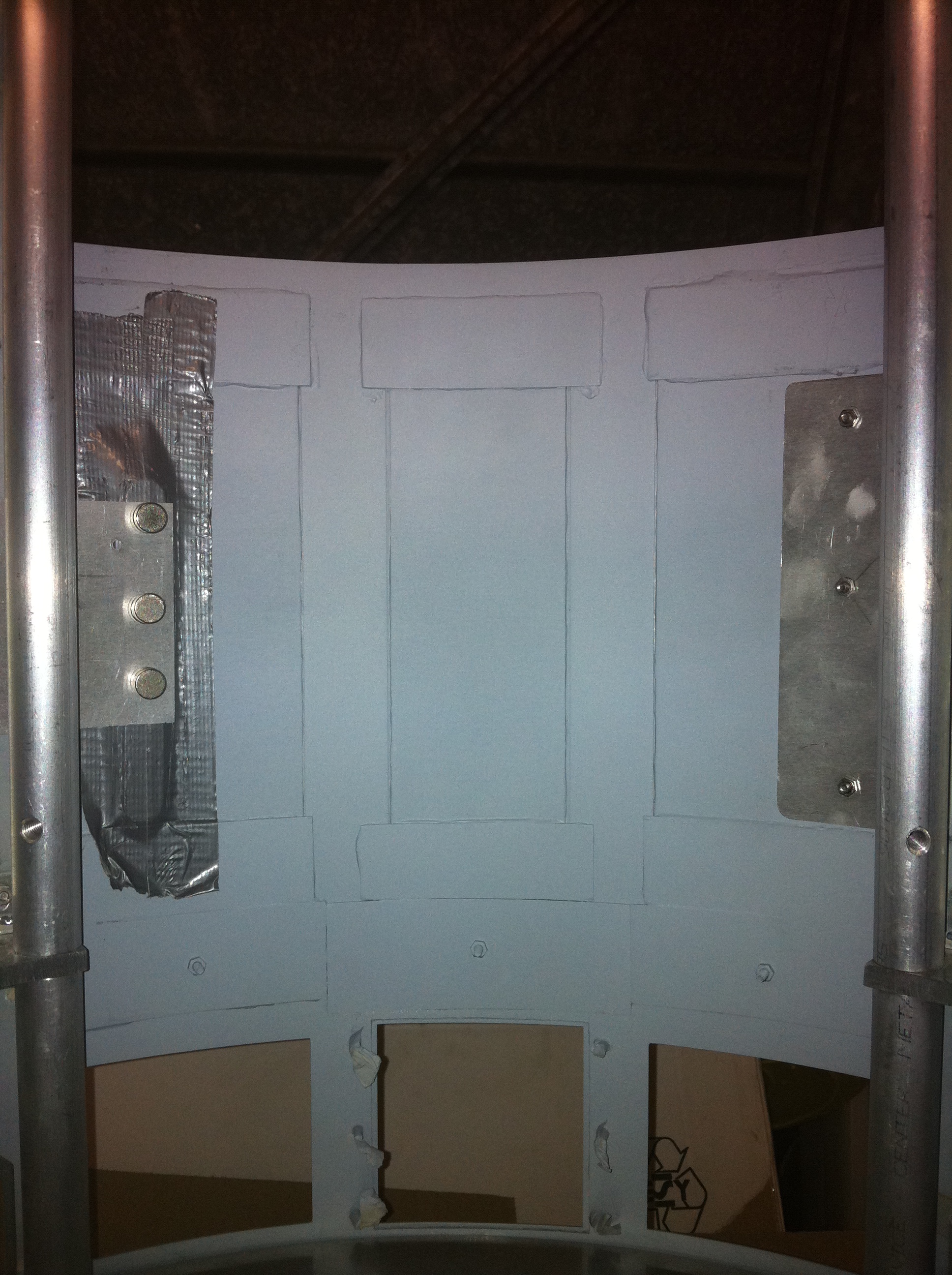
The plate on the right was used a tab to lock against the body skin. The Plate/gaffer tape was an early failed magnetic catch. I ended up with another tab that was fixed to the body and a screw was used to lock/fix the rear panel on. Below you can see the 3 fixings of the tabbed panel on the hatch. They are all filled and filed smooth ready to be repainted. Not shown is the locking screw on the right panel. sorry!
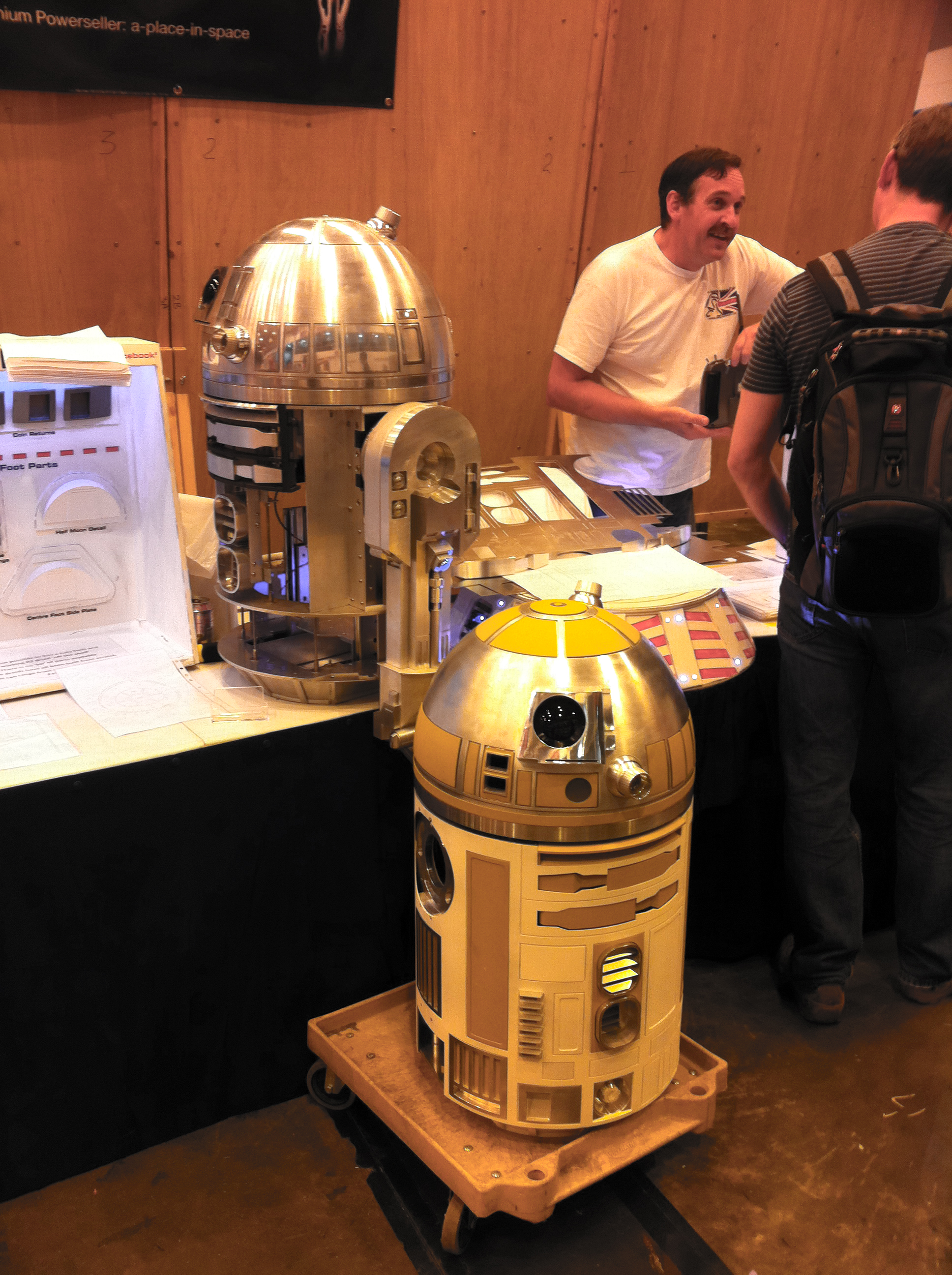
After all the painting and putting things together all the elements that I'd previously tested did go together eventually! Although I didn't have time to install the JEDI system as I seriously under estimated the time all this would take. After my 48 hour marathon build I only partly succeed. Even at the show I only displayed the body and dome as the place was so busy and the stand was so small, wasn't brave enough to bolt the legs on and drive around!
Below is a video of it all moving just to prove a point! ;)
At LLFC.
After this event and build marathon I took a long break!
Imperial Senate
During the end of July I also found time to create a new UK focused forum for all the R2 builders to share ideas and events etc.

Preparing for MEM at the NEC.Birmingham
Between the previous event and this one I decided to be a little more prepared.
So now all the JEDI lighting was installed in the dome with no major problems and wired it all together. The design I ended up with was this. The JEDI display controller, FLDs, RLD and 3 HPs were all installed in the Dome along with a the JEDI DC-DC converter to power the system. All these devices would pass through the slip ring umbilical into the body where the JEDI controller going to be mounted. The first problem I het was that I only had 1 DC-DC power supply it's best to have 2 I found out for a setup such as this. A quick search and discussion on .net help resolve a 3rd party DC supply. This allowed me to power the JEDI controller as well as the JEDI Display Controller separately and correctly it also allowed for the powering of the SERVOs on JEDI controller.
The issue I had was that umbilical between the dome and and body via the slip ring would not pass through the hole on the frame cross brace.
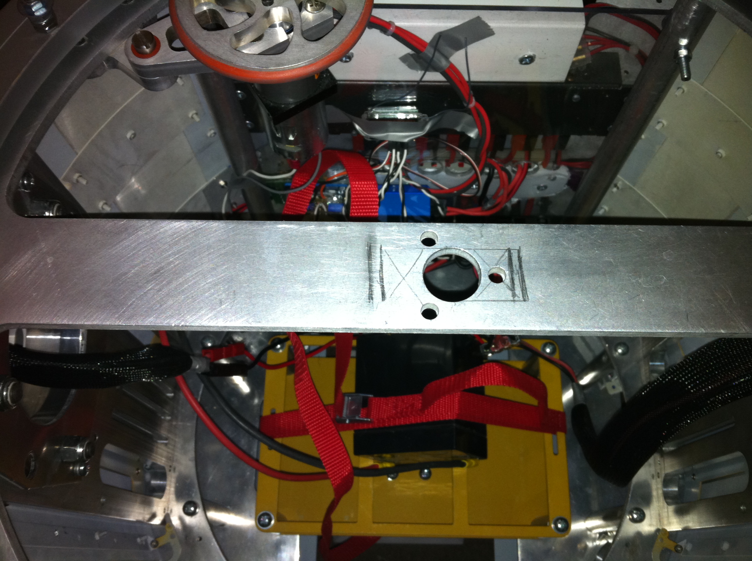
As can be seen the the rectangle marked is the size of the connector. I drilled out the hole on the right and made it large make a keyhole shape with the large centre hole. Although not perfect it is easier to pass the the cable without the connector housing. I still need to return to this to fix it!
Main Reactor on the north side...
About this time I had several ideas and decided not to follow the "pack" of most builders and looked into new systems and methods. One such change was the batteries being used. I had the standard SLA 12V,7ah batteries setup which as most will know weigh a lot! I looked into Lithium Ion batteries and "racing" batteries which are considerably lighter and deliver the same or better power. I ended up getting a Trancer 16Ah LiFePO4 state of the art gold caddy battery. It seemed logical as I did not have a good charger for the SLA battery (approx £80) and the the Trancer came with everything you needed including the Anderson connectors! It is about half the weight and just a bit larger than of a 7Ah SLA battery :) So far this has worked well although I have not done a huge amount of driving around with it. so will update later.

Control Control you must learn control!
From the many shows and also playing with my now setup JEDI system I discovered how hard it was to control R2 other functions. This led to me want to create an interface of some kind to control R2 :)
After lots of research I ended up with iPhone 4 and making a interface. The tricky part was getting the iPhone to talk to something that would talk to the JEDI system!
I also want an easy way to access this while still diving R2 with the standard RC transmitter. ( I don't feel confident driving a 60Kg droid around via a wifi signal!).
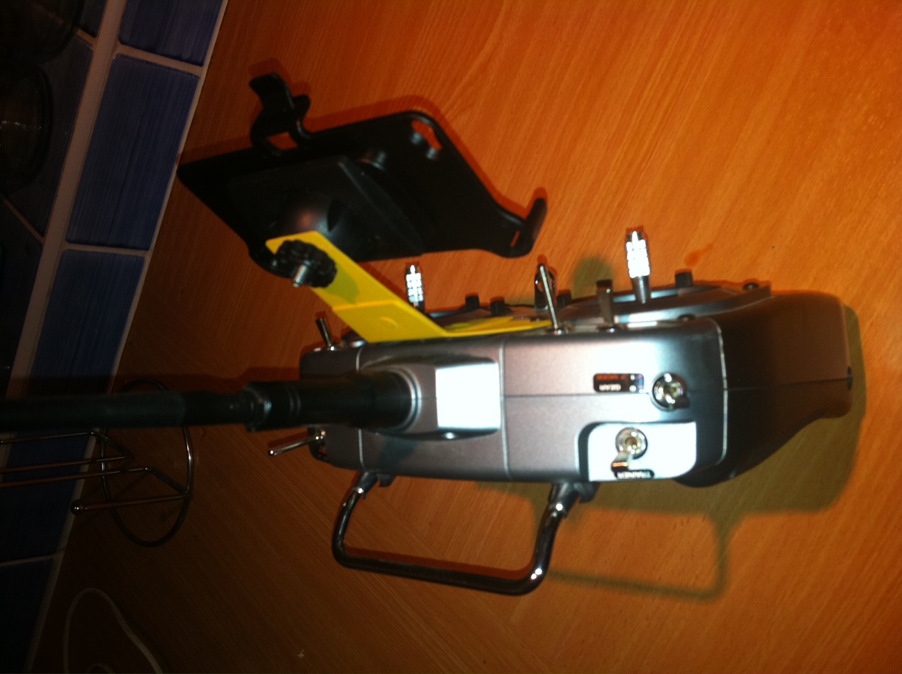
Using a car SatNav holder I chopped up and mounted it on the Spektrum 6i transmitter using some left over bits from the skins.
Here are a series of videos showing my progress.
Early setup with just button functionality.
Slightly more evolved GUI to make it more like a device from the Star Wars universe.
Another update.
I first showed the other members this progress at MEM in November
Jan 2012:
Now that I had the control method sorted I moved on from just light and sounds control to mechanical systems of the servos and main motor controller.
Speaker installation
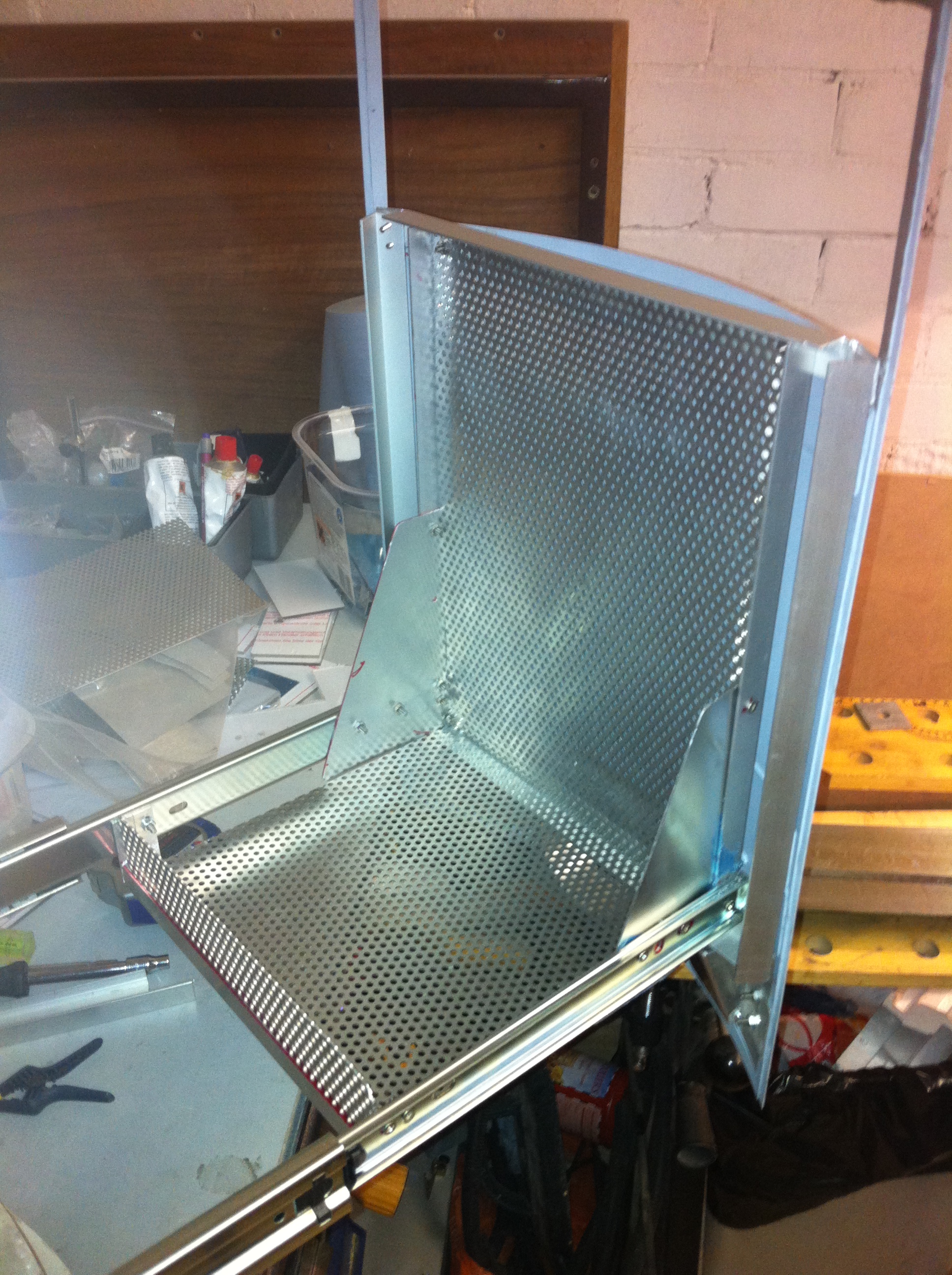
As things are progressing my desire to reduce weight from R2 is become an almost obsession! So here my latest idea of using folding sheet Alu for everything!!
I managed to get a copy of Softworks which does sheet metal modelling which helps you build something in 3D and see how it would be made from a single sheet. After buying a metal brake (the tool used to bend sheet cleanly). Here are my tests for a speaker mounting system. I decided to again do it different and mount the speakers in the sides of R2 where the blank panels are.
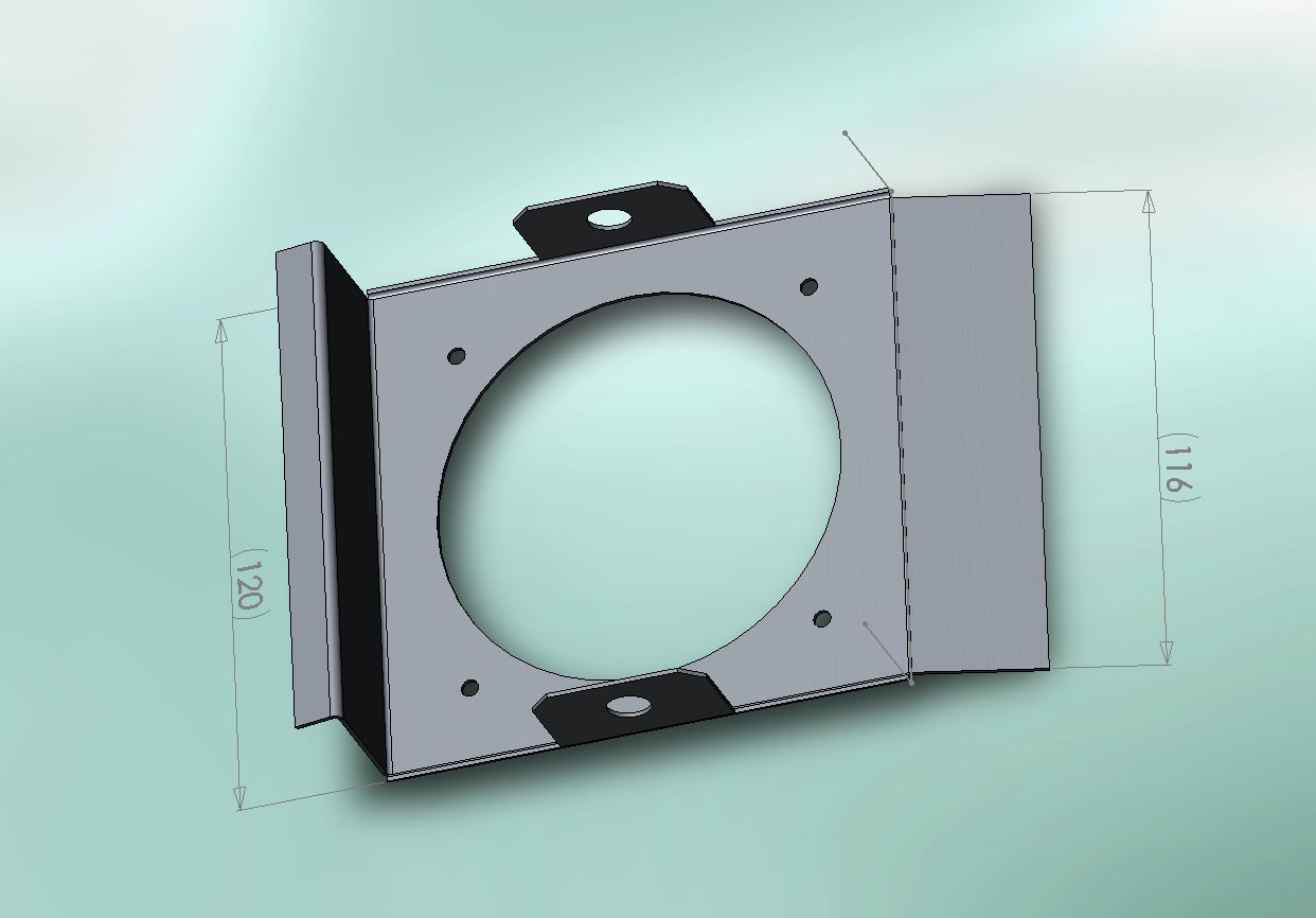
Initial design that I ended up scrapping. here the folds on the right would be fixed to the uprights of the frame.
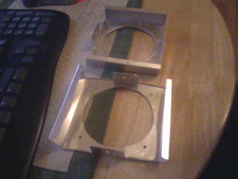
I thought this was the answer, but when installing these into the frame and speaker cones and covering mesh proved a nightmare to assemble. so along came design 3!
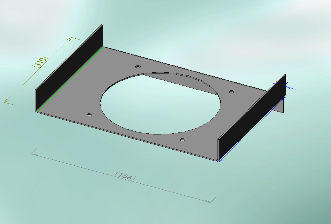
A much simpler design and much better. 4 screws mount the speaker to plate and a further 4 mount the cover perforated Alu sheet cover and this plate to the frame uprights. One is installed on both sides of the frame for Stereo sound!
"My people will get right on it..."
After all this playing around and installing the sound system, JEDI, system, Wifi control system and power system I realize how much a pain it was get into R2 and working on it. I was squeezing my hands through door panels, pie panels and shoulder apertures to reach components. Of course soon these would all have things in them too so access would become almost impossible, so I needed a solution...
This is where I came up with the idea of a slide out compartment with everything on it. I quickly got to work and design a setup with drawer slides attached to the large rear panel.
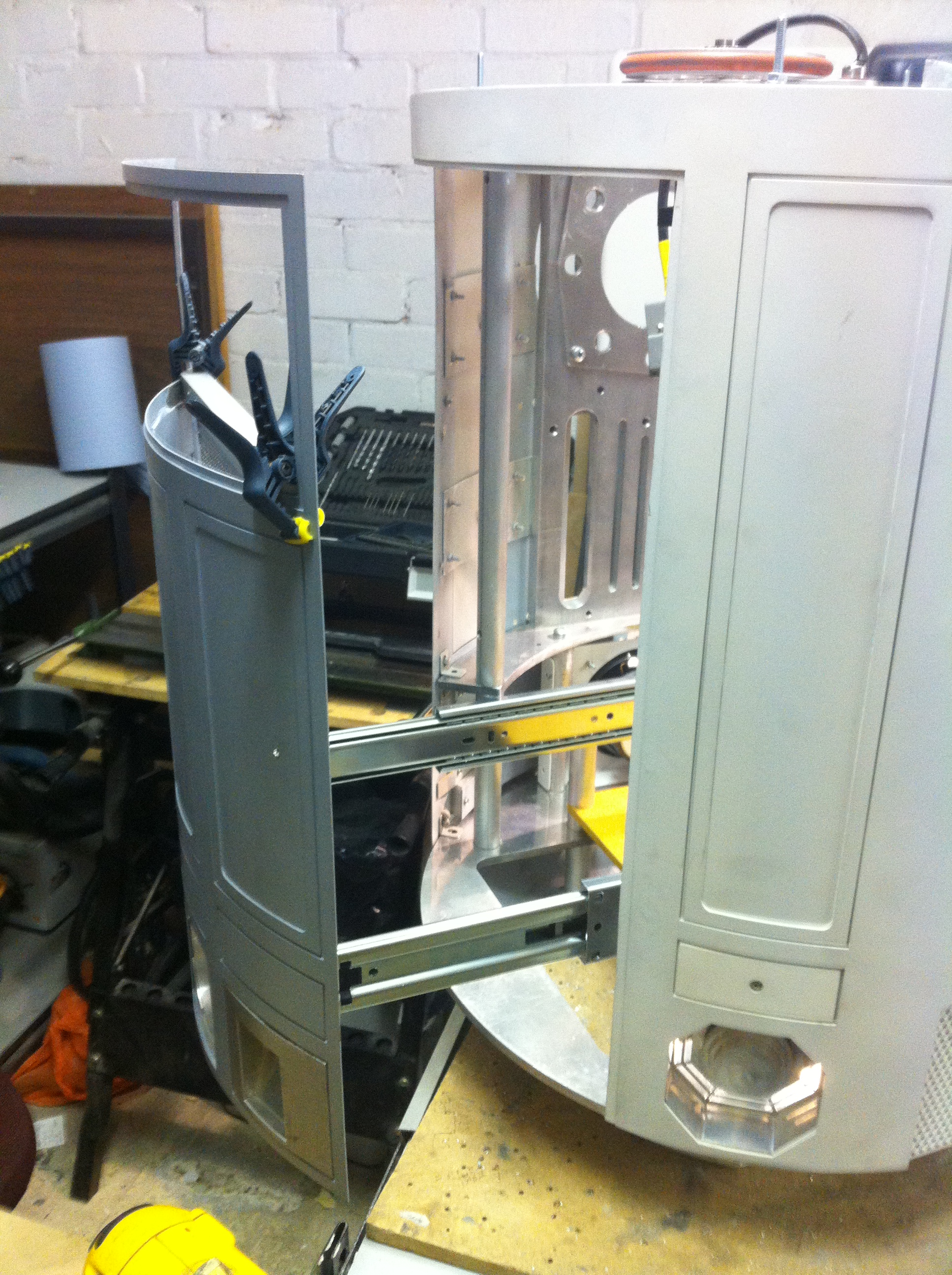
This worked fine once all fitted and bolted to the frame. However I still needed to be able to attach things to this. After searching in vain I decided to construct it myself out of sheet Aluminium and angled Alu from B&Q and ended up with this.
Here you see the unloaded "drawer" with strengthening to reduce wobble. It still needs work and I will eventually extend the frame to the full height on the panel. Even when loaded it is extremely stable, just need a method to lock it closed.
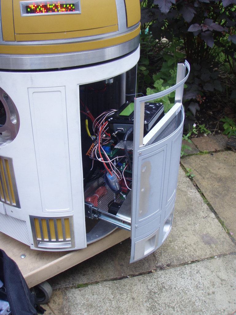
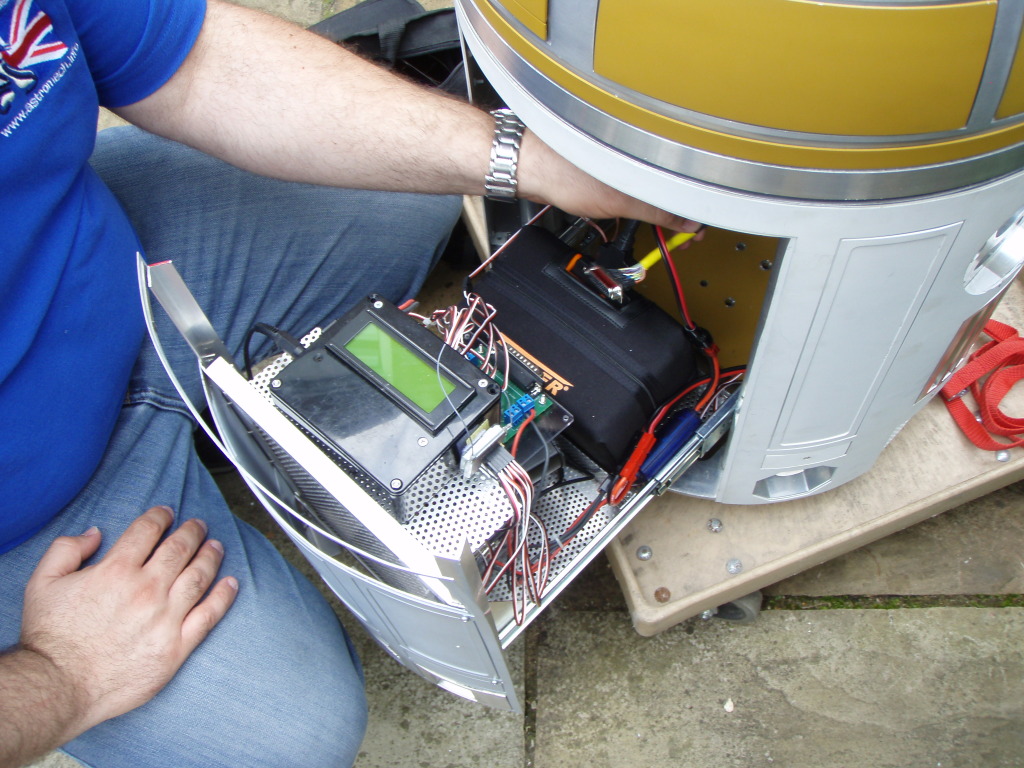
Nice and easy to access everything. The electronics are simply stacked on the drawer from the previous setup and I have yet to redesign them on the drawer system. Also my power board (which is inside R2 in the photo) needs to be rebuilt on the drawer. This will be the next step of my build...